Overview

Digital Clock using 7 segment LED showing time: 12:47 pm

Take a look at the clock here. Instead of having hands at the clock, we got a digital version of showing the time. The digital component that shows every number here is called the seven / 7-segment display. In this article, we will learn how to work with seven-segment display and Arduino.

The seven-segment display is a device that combines 8 LEDs and forms a pattern that is capable of displaying decimal numerals plus a decimal point. This device is commonly used in digital clocks, digital electronic meters, and electronic boards.

Generally, there are two types of LED seven-segment display called: Common Cathode (CC) and Common Anode (CA) [1]. The common cathode, as its name implies, common cathode seven-segment display has all of the seven-segment cathodes connected directly together, but the common anode, which is lighted as follows, has all of the seven-segment anodes connected together.

The label of 7-segment LED

Before that, let us take a look at the parts of the seven-segment LED [2]. As shown in the diagram here, a seven-segment LED consist of 3 parts:

  • Light-emitting components (a–g): Segments (Seg)
  • Dot light-emitting component: Decimal point (DP)
  • General name for the seven segments a–g: Digits (Dig)

So, the first type of seven-segment display introduced here is called common cathode (CC). All of the cathode connections of the LED segment are connected to logic "0" or ground. By applying a "HIGH," or logic "1" signal through a current-limiting resistor to forward bias each anode terminal (a-g), the individual segments are lighted (a-g).

For the second type, which is called common anode (CA), all the anode connections of the LED segments are joined together to logic “1” or, we can say that the positive voltage source is shared by the display segments. The individual segments are lighted by applying a Ground, logic “0” or “LOW” signal via a suitable current limiting resistor to the cathode of the particular segment (a-g). This means that the segments are lit by setting their individual pins to Ground.

Common Anode 7-segment LED

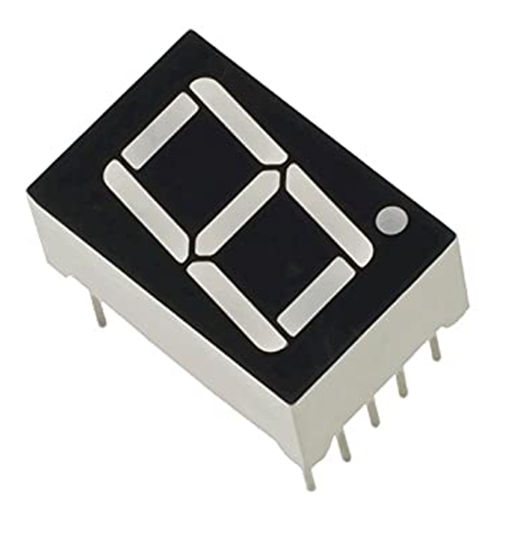
In this experiment, we will be using common anode (CA) seven segment LED. Details shown below are some information about the 7-segment LED:

  • Size : 0.56-inch
  • Emitting color : Red (Ultra-Bright )
  • Mode : Common-Anode (CA)
  • Digit : Single Digit
  • Category : LED 7-Segment Display
Common Anode 7-segment LED pin out label (a, b, c, d, e, f, g, f, GND)

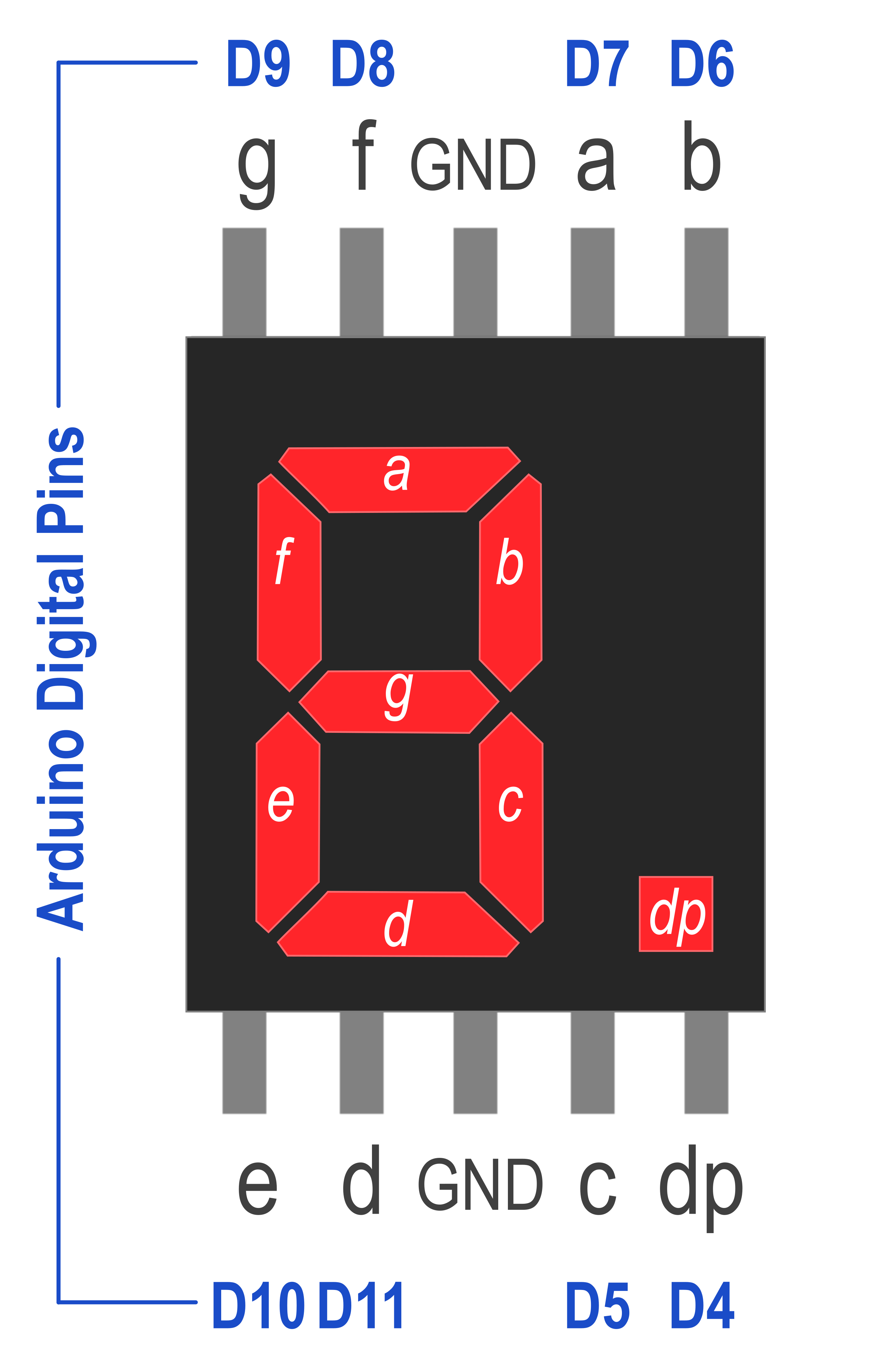
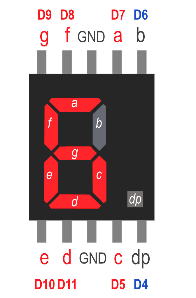
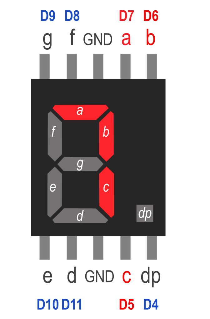
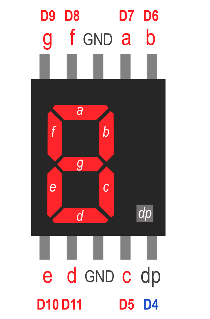
The pin for the above 7-segment LED display is presented in figure here.

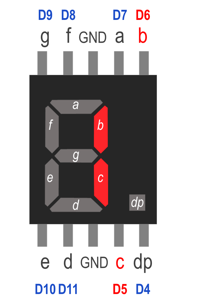
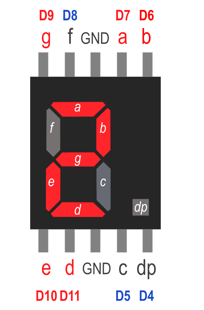
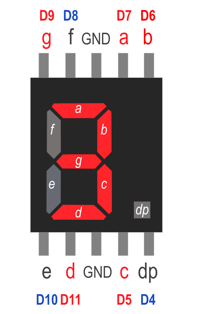
So, the purpose of this experiment is to display every digit number starting from number 1 until 9 with 1 second time interval.

Circuit Construction Planning

Common Anode 7-segment LED pin out label (a, b, c, d, e, f, g, f, GND)

First, we need to know that the 7-segment display consists of 7 individual LEDs that can be combined to display a number or a letter and another LED that represents a decimal point as represented in the figure ‎below. So, there will be 8 LEDs in total.

Secondly, we need to treat each LED as a single LED circuit. That means we will need to put a resistor in each circuit so that the LED will not burn. We used 8 units of 330-ohm resistors (color code: orange, orange, brown. You can refer to the resistor calculator for further information), connected to every LED.

With these two points in mind, we just need to connect each LED to its corresponding Arduino pins. So, in this experiment, we will be using 8 Arduino digital pins; D4, D5, D6, D7, D8, D9, D10, and D11. The mapping of LED pins to digital pins is presented in the following table, together with the diagram shown below:

Common Anode 7-segment LED pin out label (a, b, c, d, e, f, g, f, GND)
7 Segment Pin Arduino Digital Pin
a D7
b D6
b D6
c D5
d D11
e D10
f D8
g D9
dp D4

From the table, we should plan out the LED display mapping, for instance, if we want to display number one, we need to set LED b and c to ‘HIGH’. In this case, since pin b is connected to D6, and pin c is connected to D5, therefore, both D6 and D5 is the corresponding pin that need to be set to ‘HIGH/1’. Meanwhile, the other pins (D4, D7, D8, D9, D10 and D11) need to be set to ‘LOW/0’.

Displaying Number 1

7-segment LED displaying number 1
  • Pin set to HIGH/1: D5, D6
  • Pin set to LOW/0: D4, D7, D8, D9, D10, D11

Displaying Number 2

7-segment LED displaying number 2
  • Pin set to HIGH/1: D6, D7, D9, D10, D11
  • Pin set to LOW/0: D4, D5, D8

Displaying Number 3

7-segment LED displaying number 3
  • Pin set to HIGH/1: D5, D6, D7, D9, D11
  • Pin set to LOW/0: D4, D8, D10

Displaying Number 4

7-segment LED displaying number 4
  • Pin set to HIGH/1: D5, D6, D8, D9
  • Pin set to LOW/0: D4, D7, D10, D11

Displaying Number 5

7-segment LED displaying number 5
  • Pin set to HIGH/1: D5, D7, D8, D9, D11
  • Pin set to LOW/0: D4, D6, D10

Displaying Number 6

7-segment LED displaying number 6
  • Pin set to HIGH/1:D5, D7, D8, D9, D10, D11
  • Pin set to LOW/0: D4, D6

Displaying Number 7

7-segment LED displaying number 7
  • Pin set to HIGH/1: D5, D6, D7
  • Pin set to LOW/0: D4, D8, D9, D10, D11

Displaying Number 8

7-segment LED displaying number 8
  • Pin set to HIGH/1: D5, D6, D7, D8, D9, D10, D11
  • Pin set to LOW/0: D4

Displaying Number 9

7-segment LED displaying number 9
  • Pin set to HIGH/1: D5, D6, D7, D8, D9, D11
  • Pin set to LOW/0: D4, D10

Now that we have complete our mapping plan, we can proceed to constructing our circuit.

What You Need?

Before starting the experiment, you may prepare the following components :

  • 1 units of 7-segment display
  • 8 units of 330 ohm resistor (Orange-Orange-Brown-Gold)
  • 1 unit of solderless breadboard
  • 1 unit of Arduino UNO board
  • 12 units of jumper wires (male-to-male)
Electronic components required for building blinking LED circuit (7-segment display (Common Anode), jumper wires, 330 ohm resistors, a solderless breadboard, and Arduino UNO board)

Hardware Setup

Now that we already covered the basic stuff, it’s time to construct our circuit. The hardware setup for this experiment is shown in the figure below.

Setting up experiment for 7-segment LED (Common Anode) with Arduino UNO (required component: 7-segment display (Common Anode), jumper wires, 330 ohm resistors, a solderless breadboard, and Arduino UNO board)

How It Works? (Hardware Setup)

As stated above, the 7-segment display is built up by LED’s positioned to make shapes of numbers and alphabets. To show a specific number, we will need to turn on the correct combination of segments. This part is taken care of in the software where we will set HIGH and LOW states for the correct digital pins of the Arduino board.

Software Setup

In the Arduino IDE, open up a new sketch in the IDE and type the following code for the experiment.

void digitalSetLow (int pinNo[], int sizeOfArray)
{
  // This function is used to TURN ON specific LED in 7-segment display
  for(int j=0;j<=sizeOfArray;j++)
      digitalWrite (pinNo[j], LOW);
}
void resetLED()
{
  // This function is used to TURN OFF all LED in 7-segment display
  int reset[] = {4,5,6,7,8,9,10,11};
  for(int j=0;j<=8;j++)
     digitalWrite (reset[j], HIGH);
}

void setup() {
  // put your setup code here, to run once:
  int i;
  for(i=4;i<=11;i++)
      pinMode (i,OUTPUT);
  resetLED();
}

void loop() {
  // put your main code here, to run repeatedly:
  // Reference pin number (7segment,Digitalpin): dp4 c5 b6 a7 f8 g9 e10 d11

  // intializing LED for diplaying number 1
  int dn1on[] = {5,6};
  digitalSetLow (dn1on, 2); // turn on LED set above

  delay(1000);
  resetLED();

  // intializing LED for diplaying number 2
  int dn2on[] = {6,7,9,10,11};
  digitalSetLow (dn2on, 5); // turn on LED set above

  delay(1000);
  resetLED();
  // intializing LED for diplaying number 3
  int dn3on[] = {5,6,7,9,11};
  digitalSetLow (dn3on, 5); // turn on LED set above

  delay(1000);
  resetLED();

  // intializing LED for diplaying number 4
  int dn4on[] = {5,6,8,9};
  digitalSetLow (dn4on, 4); // turn on LED set above

  delay(1000);
  resetLED();

  // intializing LED for diplaying number 5
  int dn5on[] = {5,7,8,9,11};
  digitalSetLow (dn5on, 5); // turn on LED set above

  delay(1000);
  resetLED();

  // intializing LED for diplaying number 6
  int dn6on[] = {5,7,8,9,10,11};
  digitalSetLow (dn6on, 6); // turn on LED set above

  delay(1000);
  resetLED();

  // intializing LED for diplaying number 7
  int dn7on[] = {5,6,7};
  digitalSetLow (dn7on, 3); // turn on LED set above

  delay(1000);
  resetLED();

  // intializing LED for diplaying number 8
  int dn8on[] = {5,6,7,8,9,10,11};
  digitalSetLow (dn8on, 7); // turn on LED set above

  delay(1000);
  resetLED();

  // intializing LED for diplaying number 9
  int dn9on[] = {5,6,7,8,9,11};
  digitalSetLow (dn9on, 6); // turn on LED set above

  delay(1000);
  resetLED();
}

How it Works? (Software Setup)

In this sketch, we introduce a few of new things in the programming. In this section, we will cover function and passing array to function.

What is Function?

In programming, we can think of a function as a module that take in data, process it, and then, return the result. Take a simple subtraction task in calculator as an example. If the subtraction process is in the form of function, it may be translated as displayed in the figure ‎below.

An example/ analogy of using function - calculator function

Firstly, we need to declare a function, where in this case, we declare the function as: int subtract(int num1, int num2). This means that function name subtract will return an integer value and will be passed with two integer numbers. If we want to modify this function to not return any value, we can just write it as void subtract(int num1, int num2). But this will surely need some modification in the internal code within this function. Now, we need to know how to call this function in the main code. To use it, we can write it as per shown in the main function section, in Figure above: answer = subtract(9,3);. This line of code will pass value 9 and 3 to function subtract, and finally, answer will contain the result of subtraction which is 6.

The structure of a function in Arduino can be written using the following format:-

return type function name (argument 1, argument 2, … )
{
 statement
}

Therefore, in this experiment, we will be using two functions which are void digitalSetLow(int pinNo[], int sizeOfArray) and void resetLED(). Notice that both functions does not return any value.

void digitalSetLow (int pinNo[], int sizeOfArray)
{
 // This function is used to TURN ON specific LED in 7-segment display
  for(int j=0;j<=sizeOfArray;j++)
      digitalWrite (pinNo[j], LOW);
}
void resetLED()
{
  // This function is used to TURN OFF all LED in 7-segment display
  int reset[] = {4,5,6,7,8,9,10,11};
  for(int j=0;j<=8;j++)
     digitalWrite (reset[j], HIGH);
}

Based on the connection between Arduino pin and 7-segment pin, we can set which LED segment that we want to turn on as explained before.

To recap, for instance, if we want to display number 1, we need to turn on 7-segment pin label b and c. To turn it on, we need to initialize an array and pass the array to digitalSetLow function as shown below:

int dn1on[] = {5,6};
  digitalSetLow (dn1on, 2); // turn on LED set above

Notice that each and every time we set a number, there are a reset function (resetLED()). This is used to turn off all LEDs in 7-segment display.

Why We Use Function?

In programming, there are a lot of situations in which we need to reuse a part of code that have similar purpose. In addition, we may want to organize our code neatly in the future. Here are some of the advantages of using function in programming:

Functions allow programmer to divide a specific code into various section and each section performs a particular task. Functions are made to perform a task multiple times in a program.

End Of Article

End Of Article